LC UPC Duplex OS2 Shuttered Fiber Adapter with Flange
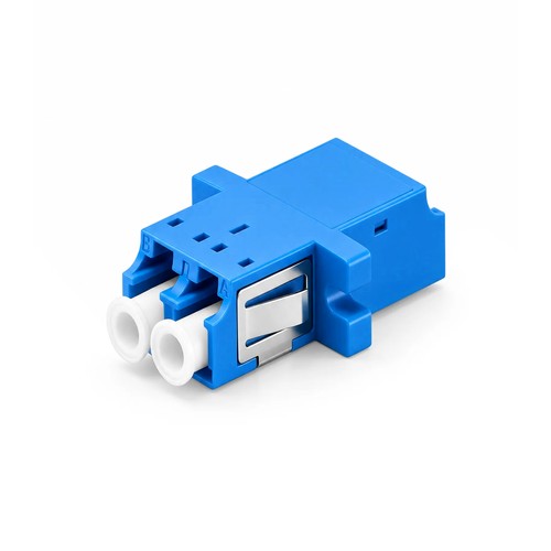
For Pakistani procurement and engineering teams, the specification provides a practical basis for checking compatibility before production is requested. LC UPC Duplex OS2 Shuttered Fiber Adapter with Flange couples two LC connectors into one continuous optical route. Inside the housing, a zirconia ceramic sleeve holds the two ferrules on a common axis, keeping insertion loss low and stable across hundreds of mating cycles. The flanged housing screws directly to this adapter panel cutout for a permanent, vibration-proof mounting. An internal shutter closes automatically when the optical interface is withdrawn, blocking dust and protecting eyes from exposed laser light.
Product Highlights
- Stainless Steel Clips for Tool-less Snap-in Installation
- ≤0.2dB (Typical) Low Insertion Loss
- Color Coded for Rapid Fiber Management
- Provides Dust Protection Without Removing or Storing the Dust Caps
- Protect Eyes from Laser Exposure, Ensuring a Safer Installation
Specifications
| Connector Type | LC-LC |
|---|---|
| Body Style | Duplex |
| Polish Type | UPC |
| Fiber Mode | OS2 9/125μm |
| Insertion Loss | ≤0.2dB |
| Durability | 500 times |
| Mounting Type | Full Flanged |
| Color | Blue |
| Flammability Rate | UL 94V-0 |
| RoHS Compliancy Status | Compliant |
| Operating Temperature | -40 to 75°C (-40 to 167°F) |
| Storage Temperature | -40 to 75°C (-40 to 167°F) |
| Shuttered Fiber Optic Adapter Datasheet | New |
| Compliance Center | Test Center |
Why the alignment sleeve decides adapter quality
Each optical adapter is, at heart, a sleeve alignment problem: two connector ferrules must meet on one axis with their end faces touching, and any eccentricity shows up directly as insertion loss. Zirconia ceramic is the standard sleeve material since it machines to sub-micron tolerance, resists wear across repeated matings and holds its dimensions through temperature swings. The adapters in this range use zirconia sleeves rated for insertion loss of 0.2 dB or better, which keeps an adapter pair well inside any optical loss calculation.
Flanged and flangeless mounting compared
A flanged adapter fastens to this adapter panel with two screws through the mounting ears: the joint is rigid, resists vibration and stays put for years, which suits frames and enclosures that move or ship. A flangeless adapter snaps into the cutout on spring latches: unit is faster, density is higher, and a failed adapter swaps out in seconds without tools. Most panel families accept one style or the other, and therefore the option follows this adapter panel hardware already in the plant.
UPC and APC discipline at the adapter
The adapter housing has no polish of its own, but it is where polish discipline succeeds or fails: mating a UPC connector to an APC connector through any adapter damages the two end faces and wrecks return loss. Color coding exists to prevent exactly that - green housings for APC, blue for UPC single-mode - and the discipline only works when the whole plant follows it. Keep the adapter housing color, the optical interface boot color and the documentation consistent, and the mixing mistake becomes nearly impossible.
Shuttered adapters in live environments
An open adapter port is an invitation to dust, and dust on a ferrule end face is the single most common cause of unexplained loss. A shuttered adapter closes an internal flap the moment the optical interface withdraws, keeping the sleeve bore clean until the next mating. The identical shutter blocks the direct line of sight into a live port, a small but real safety gain where high-power transmitters are in service. Shuttered versions cost slightly more and repay it the first time a port stays clean through a long build phase.
What adapter testing actually measures
An adapter contributes no signal of its own, and therefore its test is a mating test: reference connectors mate through the adapter housing, and the inserted loss is recorded. A zirconia-sleeve adapter ought to add no more than 0.2 dB, and the mating must repeat that figure across cycles. Durability testing runs the mating hundreds of times and re-measures - a sleeve that wears loose announces itself as creeping loss. These figures, not the housing color, are what separates an adapter that serves for years from one that becomes the mystery fault.
Selecting the right adapter for the panel
Five decisions define the adapter housing order: the optical interface pairing must be aligned with the two sides of the mating, the mounting style must fit this adapter panel cutout, the polish color code must be aligned with the plant, the sleeve material must suit the behavior grade, and the count must cover the load-out plus spares. Getting all five right at order time is what turns a bag of couplers into a dependable panel. Where the pairing crosses connector families, the hybrid range covers the common conversions.
Test Standards and Quality Control
Each adapter is inspected before packing: the sleeve bore is checked for alignment and surface finish, the housing latches are cycled for positive engagement, and sample matings from every production lot are measured for insertion loss. Accessories are checked for fit against the adapters they serve.
Ordering Details and Factory Support
Refer to this adapter by connector pairing, mounting style, polish grade and pack number of units when specifying a quotation. For configurations outside the listed options - mixed packs, panel hardware kits or project packing - send the specification with the request and the factory will make certain of the manufacturable specification. For Pakistan, a clear port or maintenance schedule helps us confirm the correct factory-built configuration before supply.


