OSFP (IHS/Finned Top) to 4x OSFP (IHS/Finned Top)-800G-DAC-2M7FT 800G OSFP 8 x 100G PAM4 IHS/Finned Top to 4 x 200G OSFP 2 x 100G PAM4 IHS/Finned Top Passive Copper Breakout Cable, 2m (7ft)
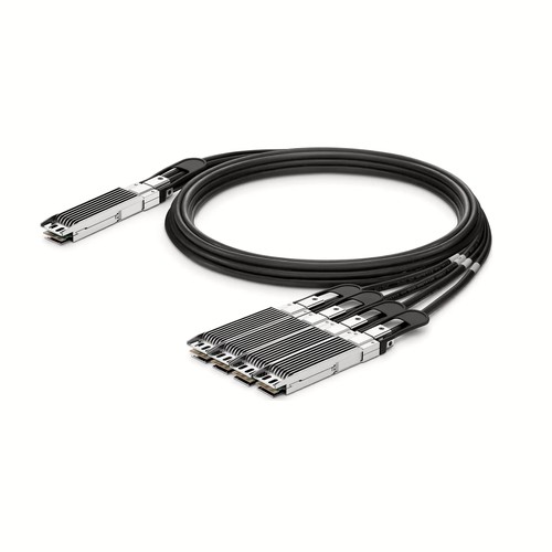
The assembly listed here is the 2m (7ft) member of the OSFP (IHS/Finned Top) to 4x OSFP (IHS/Finned Top)-800G-DAC-2M7FT product family for Generic equipment. It provides 800G DAC connectivity through OSFP (IHS/Finned Top) to 4x OSFP (IHS/Finned Top). Project teams can use the detailed table, related references and documentation-oriented packing information to keep each delivered cable aligned with its planned endpoints.
OEM Part Number: OSFP (IHS/Finned Top) to 4x OSFP (IHS/Finned Top)-800G-DAC-2M7FTHT Part Number: OSFP (IHS/Finned Top) to 4x OSFP (IHS/Finned Top)-800G-DAC-2M7FT
Product Highlights
- HT-manufactured DAC assembly in 2m (7ft)
- 800G connectivity at 800Gbps
- Interface configuration: OSFP (IHS/Finned Top) to 4x OSFP (IHS/Finned Top)
- Fixed length and part number: 2m (7ft), OSFP (IHS/Finned Top) to 4x OSFP (IHS/Finned Top)-800G-DAC-2M7FT
- Cable construction: Passive Breakout DAC
- Conductor specification: 28AWG
- Maximum power consumption: 0.1W (800G End), 0.1W (200G Per End)
- Minimum bend radius: 31mm
Specifications
| HT Part Number | OSFP (IHS/Finned Top) to 4x OSFP (IHS/Finned Top)-800G-DAC-2M7FT |
|---|---|
| Manufacturer | HT |
| Form Factor | OSFP (IHS/Finned Top) to 4x OSFP (IHS/Finned Top) |
| Max. Data Rate | 800Gbps |
| Media | Copper |
| Cable Type | Passive Breakout DAC |
| Cable Length | 2m (7ft) |
| Wire AWG | 28AWG |
| Minimum Bend Radius | 31mm |
| Max. Power Consumption | 0.1W (800G End), 0.1W (200G Per End) |
| Jacket Material | PVC (OFNR) |
| Commercial Temperature Range | 0 to 70°C (32 to 158°F) |
| Modulation Format | 8x100G-PAM4 to Quad 2x100G-PAM4 |
| Application | 800G/200G Ethernet |
| Protocols | OSFP MSA, CMIS Rev4.0, IEEE 802.3ck |
Signal and Lane Configuration
The listed modulation format is 8x100G-PAM4 to Quad 2x100G-PAM4. Both host interfaces must be configured for the same aggregate rate and lane arrangement. A connector that fits mechanically does not by itself guarantee that the remote port supports this encoding or breakout mode.
Length Selection and Installation Planning
OSFP (IHS/Finned Top) to 4x OSFP (IHS/Finned Top)-800G-DAC-2M7FT provides 2m (7ft) for connections between separated rack units or nearby equipment positions. Plan the route around cable managers and power cords, keeping the assembly free from connector strain while avoiding a large obstruction in the airflow path.
Position Within the Length Range
OSFP (IHS/Finned Top) to 4x OSFP (IHS/Finned Top)-800G-DAC-2M7FT is the longest of 4 verified length options in this family. Compared with OSFP (IHS/Finned Top) to 4x OSFP (IHS/Finned Top)-800G-DAC-1.5M5FT at 1.5m (5ft), it provides 0.5m of additional reach for a longer vertical drop, a wider rack or an adjacent-cabinet route. Confirm that the complete path requires this length, because unused slack still needs supported, bend-safe storage.
Project Documentation and Cable Identification
Large deployments are easier to audit when the order code, physical length and endpoint record agree. Keep the OEM reference in the compatibility document and use the HT part number on the packing list. Where several lengths arrive together, labels and carton groups can be arranged by rack or port plan so installers do not have to identify cables by appearance alone. For this assembly, the listed conductor specification is 28AWG; the minimum bend radius is 31mm; the stated power consumption is 0.1W (800G End), 0.1W (200G Per End); the jacket material is PVC (OFNR).
Power and Thermal Planning
The rated power consumption is 0.1W (800G End), 0.1W (200G Per End). Include this load in the host-port power and thermal budget, especially in densely populated switches. Maintain front-panel clearance and do not bundle the cable so tightly that it obstructs airflow around the connectors.
Cable Construction and Routing
This assembly uses 28AWG conductors, PVC (OFNR) jacket, minimum bend radius 31mm. These mechanical characteristics affect how the cable should be dressed behind the equipment. Avoid sharp edges, excessive ties and repeated tight bends close to the connector boots.
Network and Protocol Considerations
The intended application is 800G/200G Ethernet. Listed interface and protocol references include OSFP MSA, CMIS Rev4.0, IEEE 802.3ck. Confirm that the host firmware and port configuration support the same operating mode.
Breakout Port Mapping
The OSFP (IHS/Finned Top) to 4x OSFP (IHS/Finned Top) configuration divides the high-speed interface into multiple lower-speed connections. Verify the upstream lane assignment, downstream port speeds and breakout setting on the host before connecting the assembly. Each branch must attach to the correct remote interface.
Passive Copper Operation
A passive DAC has no separate optical conversion stage. Its low-power, low-latency operation is useful for short equipment links, but the assembly must remain within the length and signaling mode accepted by both hosts.
Generic Compatibility and Factory Testing
Factory verification links the compatibility identity to the exact physical assembly described on this page. Identification, connector condition and live link behavior are checked before packing. Customers can submit equipment and firmware details with the project documentation for a more specific pre-order compatibility review. Both connectors are examined before the operating test, which includes link stability and diagnostic indications.
Frequently Asked Questions
Is this an original equipment manufacturer cable?
No. It is manufactured by HT under our own manufacturer identity.
Can excess cable be folded into a compact bundle?
No. Use a supported, bend-safe service loop and observe the listed minimum bend radius. Do not crease the cable or tighten ties around the connector boots.
Will any matching connector operate at the same speed?
Not necessarily. Both hosts must support the stated rate, identification, lane mapping and any required breakout configuration; mechanical compatibility alone is insufficient.
What details assist a compatibility review?
Provide the equipment manufacturer, model, port type, hardware revision and software release, together with the OEM reference, required length and quantity.
Ordering Information
Use the listed HT part number for ordering and retain the OEM reference as the host-compatibility cross-reference. Send quantities by length, along with any rack-based packing or label instructions. If the project has mixed equipment, include the host model for each group rather than relying only on the aggregate cable rate. This page’s fixed configuration is 2m (7ft); another length must be quoted under its corresponding part number.
Shipping and Lead Time
Available stock is generally dispatched within one to three working days after order confirmation, with production lead times advised for larger quantities. International express, air cargo and sea freight can be selected according to destination and carton volume; customer courier accounts and nominated forwarders are also accepted.
Quality Assurance and Packaging
Inspection and link testing are completed before the cable enters its protective packaging. Project orders can be packed and labelled by length, rack or customer reference, with packing documentation that makes received quantities straightforward to reconcile against the installation schedule. Volume orders can include customer references on the labels and carton list.


